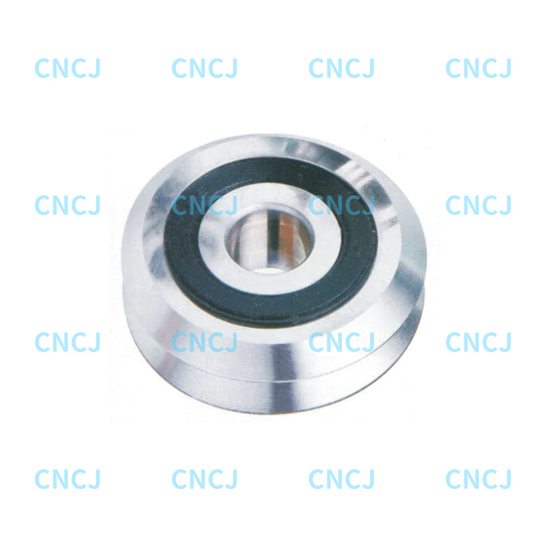
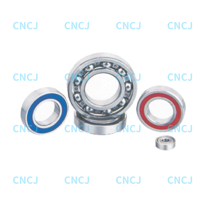
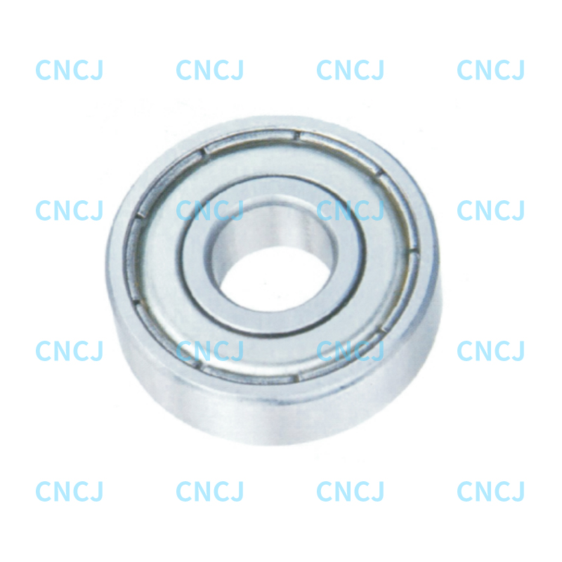
A maintenance team presses a 6205 bearing onto a shaft that was rebuilt by welding and hand turning. The bearing slides on with two light taps, so they sign the job off. Eight weeks later the shaft seat carries rust-brown fretting scars, the inner ring has crept a few degrees around its seat, and the grease is full of fine iron powder. Nothing in their bearing press fit tolerance chart was wrong. They read the wrong line of it.
A press fit tolerance chart does exactly one job. It converts a shaft or housing tolerance class into a range of interference, usually stated in microns, for a given bearing bore. It will not tell you whether that seat survives a 90 degree temperature rise, whether the ring creeps under a rotating load, or how much force the press will need. The working order is straightforward: pick the fit from load direction and rotation, look up the resulting interference, then check clearance loss and press force. Everything below follows that order.
What a Press Fit Tolerance Chart Converts
Interference is a length, not a percentage. For a bearing inner ring on a shaft it is the shaft outside diameter minus the bearing bore diameter, and a positive number means the ring has to be stretched to fit. Negative numbers describe clearance, not fit, and they are where creeping rings come from.
Nearly every published chart is built on ISO 286 tolerance classes. Shafts carry lowercase letters such as j, js, k, m, n, p and r; housings carry uppercase letters such as H, J, K, M, N and P. The digit after the letter is the grade, and grade 6 is the normal choice for bearing seats because grade 7 nearly doubles the band without buying any real benefit.
The complication most charts bury in a footnote is that a rolling bearing bore is not a nominal hole. Normal class bearings are manufactured with a bore at nominal size or smaller and never larger, so the deviation band runs from zero down to a negative limit. For a 25 mm bore that band is 0 to minus 10 microns; for a 100 mm bore it is 0 to minus 20 microns. The practical consequence is that the interference you actually get is larger than the shaft deviation alone suggests, and the spread between the loosest and the tightest assembly is wider than most designers assume.
The bearing bore bands come from the normal tolerance class, and the interference figures stack the full negative bore band against the shaft deviation, so the right column describes a worst-case range rather than one fixed value.
Bearing bore (mm)
Bore tolerance (microns)
Shaft fit
Resulting interference (microns)
10 to 18
0 to minus 8
k6
1 to 20
18 to 30
0 to minus 10
k6
2 to 25
18 to 30
0 to minus 10
m6
8 to 31
30 to 50
0 to minus 12
m6
9 to 37
50 to 80
0 to minus 15
n6
20 to 54
80 to 120
0 to minus 20
n6
23 to 65
Look at how wide that right-hand column is. A 30 to 50 mm seat on an m6 shaft can end up with 9 microns or 37 microns, depending on where the shaft and the ring land inside their own tolerance bands. If a design only works at one end of that range, the chart has not solved the problem; it has only moved it to the shop floor.
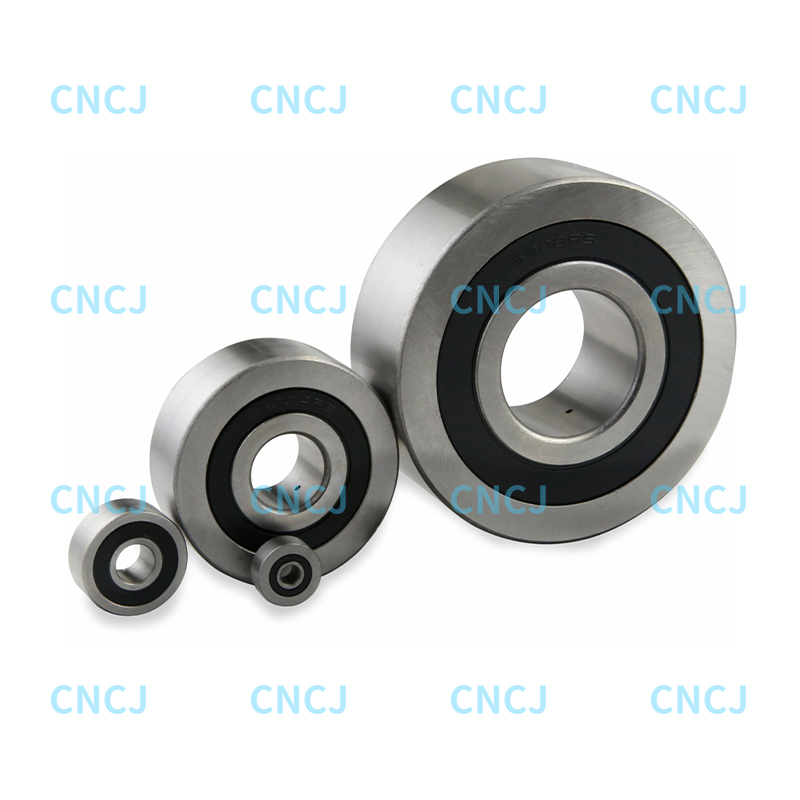
Thin-ring products suffer most from that spread. A standard deep groove ball bearing has an inner ring wall thin enough that a few extra microns of interference consume measurable internal clearance, which is why one chart line that suits a heavy-section roller bearing can be too aggressive for a small ball bearing of the same bore.
Rotation and Load Direction Decide Which Ring Is Tight
The chart gives you numbers, not decisions. The decision starts with a single question: which ring rotates relative to the load direction? Whichever ring carries a rotating load relative to the load vector must be the interference fit, because otherwise the ring creeps around its seat in small increments, wears the seat, and eventually destroys both the bore and the shaft.
On a typical electric motor or gearbox input, the inner ring rotates with the shaft while the load direction stays roughly fixed in space. That inner ring gets the tight fit, usually k6 or m6 on the shaft, and the outer ring runs in an H7 or J7 housing that allows a light push fit or even a small clearance. Flip the arrangement, as happens with a wheel hub or a pulley idler where the load rotates with the outer ring, and the logic reverses: the housing becomes the tight seat and the shaft becomes the loose one.
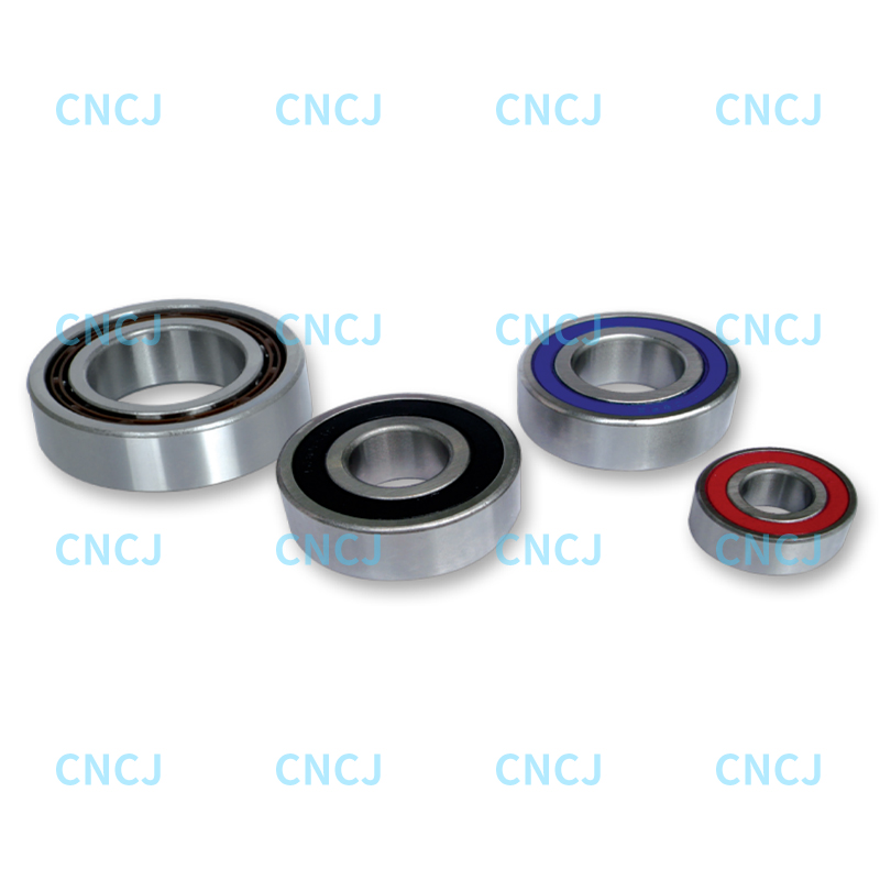
Where both rings see a rotating load, or where shock loads reverse direction, neither seat can be loose. Double row angular contact bearings are common in that situation because they take combined radial and axial loads from both directions, and their two rows share the load so the seat pressure stays moderate. Designers who specify them usually keep the shaft at m6 and the housing at N7 or P7 rather than loosening one side.
One detail is easy to overlook. A fixed-and-floating arrangement needs one bearing located axially and one that can slide, and the floating bearing must run on a clearance or transition fit so the shaft can grow without loading the rolling elements. Locking both ends with tight fits turns thermal growth into a preload problem.
Reading the Interference Numbers
Interference Does Not Scale With Bore Size
A common assumption is that doubling the bore doubles the interference. It does not, at least not for a fixed tolerance class. Grade 6 shaft deviations grow slowly with diameter because they are built from a tolerance unit that rises with the cube root of the diameter, while the bearing bore band grows in steps set by the standard. The chart below shows what that means in practice.
Figure 1. Average interference produced by an m6 shaft fit across five bore size ranges.
Read the bars as averages rather than targets. Moving from a 10 to 18 mm bore to an 80 to 120 mm bore roughly doubles the average interference, from about 13 microns to about 24 microns, while the diameter itself grows by a factor of six or more. That gap exists because the tolerance unit behind a grade 6 shaft grows far more slowly than the nominal diameter. The practical effect is that small bearings end up proportionally tighter, in terms of ring strain, than large bearings on the same fit class. This explains why a k6 seat that feels gentle behind a 100 mm bearing can feel distinctly firm behind a 15 mm bearing, and it is also why small high-speed spindles often move one grade looser. Use the bar heights to judge the direction and the size of the change, then confirm the actual limit deviations in the current edition of the standard before you cut metal.
Thermal Growth Can Erase the Fit
Interference is not permanent. When the outer ring runs hotter than the housing, or when the housing expands faster than the bearing steel, the fit loosens. The next chart shows how much of the cold interference survives as the temperature rises, for three common housing materials.
Figure 2. Percentage of the original interference retained as operating temperature rises, by housing material.
Aluminum housings are the extreme case in this comparison. Their thermal expansion is roughly twice that of bearing steel, so a housing that holds 20 microns of interference at 20 degrees can lose most of that hold by the time it reaches 80 degrees of temperature rise. A steel housing paired with a steel bearing is far more stable, because both parts grow at nearly the same rate and the fit barely moves. Cast iron sits between the two, which is one reason it remains popular for gearbox and pump housings. The lesson is that the fit has to be judged at the operating temperature, not at the assembly bench, and that any aluminum housing carrying a rotating load needs a heavier class such as m6 or n6 simply to keep contact when it is hot. Where a housing runs hot and cannot be given a heavier class, an axial locating shoulder or an end clamp is a more reliable answer than adding more interference. Temperature also explains why a bearing that was correct on the test stand can still creep in service after an upgrade in motor power.
Assembly Force, Clearance Loss and Fit Selection
Press Force Follows Interference Linearly
Press force decides whether the job is done with an arbor press, a hydraulic press or a hammer nobody should be using. It rises in a straight line with interference, which makes it easy to estimate from the chart before a single part is ordered. The values below assume a 40 mm bore bearing with a 15 mm wide inner ring pressed onto a solid steel shaft.
Figure 3. Estimated assembly force for a 40 mm bore bearing with a 15 mm wide inner ring on a solid steel shaft.
Each additional 5 microns of interference adds roughly 3.6 kN of assembly force, which is the kind of straight-line relationship you can hold in your head at the bench. The linearity is useful because it lets you size a press from the chart without running a full contact-stress calculation, and it also explains why tolerance stack-ups bite hardest during assembly. A seat designed around 15 microns can demand twice the expected force if the shaft and the ring both land at the tight end of their bands. Force is also a quality signal worth recording: if a bearing that should need 12 kN slides on by hand, the seat is undersized, and if it needs far more than the estimate, the seat is oversized, tapered or damaged. The full installation sequence for double row angular contact bearings is worth reading before any of these numbers are applied, because force should always go through the ring that is being fitted, never through the balls.
Interference alone does not rank a fit. A class that looks tight in microns may still be easy to assemble if the seat is short and the ring is small, and a class that looks moderate may be awkward if the housing is thin-walled. The radar chart below scores three common shaft classes against five practical criteria.
Figure 4. Relative scoring of three shaft fit classes against five practical selection criteria.
js6 is easy to assemble and easy to remove, but it offers the least resistance to creep, so it belongs on light, steady, essentially non-rotating loads where a locating shoulder already prevents axial movement. k6 is the general-purpose answer for normal radial loads on a rotating inner ring, and it still allows disassembly with a standard puller. m6 trades assembly convenience for a firmer grip, which is what a heavy or shock load, a thin-walled housing or an aluminum seat actually needs. None of the three wins on every axis, and that is the point of comparing them this way instead of reading a single interference figure. If vibration and creep dominate the failure history of your machine, accept the tighter assembly and plan for a proper press with a controlled force gauge. If service access is the real constraint, accept the looser class and add an axial locating feature so the ring cannot walk.
A Practical Checklist Before You Commit a Fit
Decide which ring rotates relative to the load direction. That ring gets the interference fit and the other one gets a transition or clearance fit.
Convert the bearing bore class into a deviation band. Normal class bores are never oversize, so the band always runs from zero downwards.
Check the interference at operating temperature, not at room temperature, especially with aluminum or magnesium housings.
Estimate press force from the chart and compare it with the press capacity and the mounting force the ring can safely take.
Confirm that the clearance consumed by the interference does not eat more than about half of the bearing internal clearance.
Verify that your machining process can actually hold the tolerance you specified. No chart survives a lathe that cannot hold 10 microns.
None of this replaces the standard. A chart is a shortcut through the ISO tables, and those tables change between editions. What the chart gives you is a fast way to sanity check a design before it reaches the shop floor: interference range first, thermal loss second, press force third, creep resistance last. At Ningbo Wanshun Bearing, we build deep groove and double row angular contact bearings in the 10 to 120 mm bore range, and we would much rather answer a fit question before the press is switched on than after a shaft seat has been scrapped.